VXLAN EVPN Multisite
The ability to create overlay networks that function similarly to site-to-site VPNs gives VXLAN extensibility across multiple sites without requiring dedicated links, instead utilizing ISP networks. Other technologies like MPLS offer this capability. However, using a single VXLAN protocol stack across the entire infrastructure ensures consistent configuration and can bypass ISP limitations by encapsulating frames in standard Layer 3 packets.
VXLAN EVPN multisite architecture is a VXLAN BGP EVPN design based on overlay networks. It enables the interconnection of multiple distinct VXLAN BGP EVPN fabrics or overlay domains while introducing new approaches to fabric scaling, compartmentalization, and Data Center Interconnect (DCI).
When building a large data center fabric per location, various operational and failure containment challenges arise. Creating smaller fabric compartments can improve failure isolation and operational efficiency. However, interconnecting these compartments introduces complexity, particularly when Layer 2 and Layer 3 extensions are required, making widespread adoption of such concepts difficult.
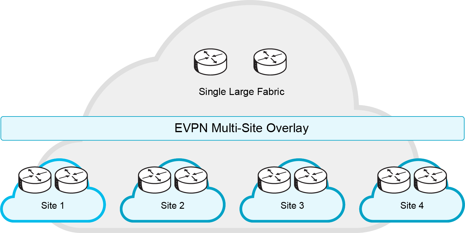
Multisite deployments use the same technology for intersite and intrasite connectivity, often requiring SDN design due to scale.
As with the compartmentalization and scale-out within a data center, the EVPN multisite architecture was built with DCI in mind.
The overall architecture allows single or multiple sites per data center to be positioned and interconnected with single or multiple sites in a remote data center. With seamless and controlled Layer 2 and Layer 3 extension using VXLAN BGP EVPN within and between sites, the capabilities of VXLAN BGP EVPN itself have been increased.
New features like network control, VTEP masking, and BUM traffic enforcement make EVPN multisite architecture highly efficient. These are just some of the reasons that it is considered the best DCI technology.
The main functional component of the EVPN multisite architecture is the border gateway, or BGW. BGWs separate the fabric-side (site-internal fabric) from the network that interconnects the sites (site-external DCI) and masks the site-internal VTEPs.
Commonly, an EVPN multisite deployment consists of two or more sites that are interconnected through a VXLAN BGP EVPN Layer 2 and Layer 3 overlay. In the scenario shown in the preceding figure, the BGW connects to site-internal VTEPs, usually through spine nodes. It also connects to an external transport network so traffic can reach BGWs at other remote sites.
The BGWs at the remote sites have site-internal VTEPs behind them. Only the underlay IP addresses of the BGWs are seen inside the transport network between the BGWs.
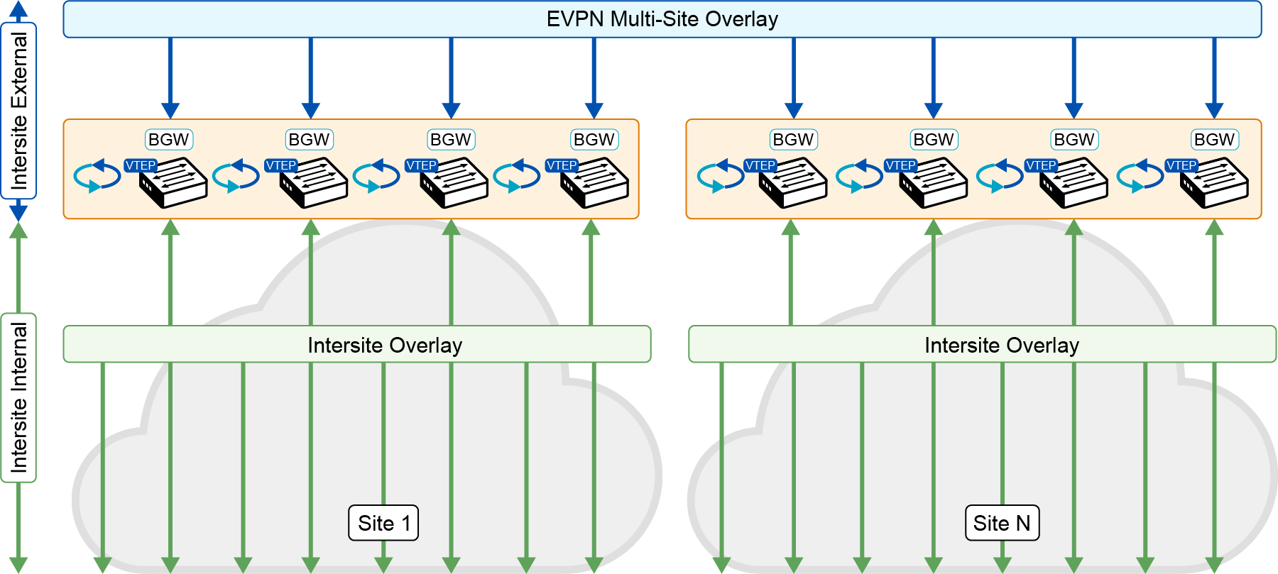
Border Gateways (BGWs) act as the endpoints for the DCI. The site-internal VTEPs are always masked behind the BGWs.
From a BGW perspective, the role of the site-internal VTEPs is to share the common VXLAN and BGP-EVPN functions. To interoperate with a BGW, a site-internal node must support the following functions.
Step 1
VXLAN with PIM ASM or ingress replication (BGP EVPN Route Type 3) in the underlay.
Step 2
BGP EVPN Route Type 2 and Route Type 5 for the overlay control plane.
Step 3
Route reflector capable of exchanging BGP EVPN Route Type 4.
Step 4
VXLAN Operation, Administration, and Maintenance (OAM)-capable devices for end-to-end OAM support.
From the point of view of the site-external network, no specific requirements are demanded apart from IP transport reachability between the BGWs and accommodation of an increased MTU packet size. BGWs always use ingress replication for Layer 2 BUM traffic between different sites. Within a site, they can use either Protocol Independent Multicast–Any Source Multicast (PIM ASM) or ingress replication. This capability provides flexibility for existing deployments and transport independence for the site-external network.
The BGW performs the internal-to-external site-separation procedure locally. Therefore, the BGW does not require a neighboring device to perform this function. Just as a traditional VTEP can connect from a site-internal network to a BGW, a traditional VTEP can also connect to a BGW from a site-external network.
A BGW at the source site does not require a neighboring BGW at the destination site; a traditional VTEP is sufficient. This flexibility is built into the BGW and allows deployments beyond the traditional EVPN multisite pairings.
| Note A traditional VTEP can connect to a BGW from an external network. However, these VTEPs do not provide extended BGW functions like site-internal VTEP masking. |
|---|
With EVPN multisite architecture, two placement locations can be considered for the BGW. A dedicated set of BGWs can be placed at the leaf layer, with the BGWs connected to the spine just like any other VTEP in the fabric (site-internal VTEPs).
Alternatively, BGWs can be collocated on the spine of the fabric. If the BGW is on the spine, many functions are overloaded together: for instance, the route-reflector, east-west traffic, and external connectivity functions. In this case, you need to consider additional factors that are related to scale, configuration, and failure scenarios.
The anycast BGW (A-BGW) performs the BGW function. The anycast BGW (A-BGW) allows the BGWs to be scaled horizontally in a scale-out model and without sharing the issues of interdevice dependencies. At the time of writing, 10 sites can be interconnected. This is a software feature and can increase with software upgrades.
The name “A-BGW” refers to the sharing of a common VIP address or anycast IP address between the BGWs in a common site. This document also uses the virtual IP address to refer to the EVPN multisite anycast IP address.
The BGW’s virtual IP address is used for all data-plane communication leaving the site. It is also used for communication between sites when the EVPN multisite extension connects to a remote site. A single virtual IP address is used within the site to reach the exit point and between sites for communication. BGWs always use this virtual IP address to talk to each other.
A dedicated loopback interface represents the virtual IP address and associates it with the network virtualization edge (NVE) interface (multisite border-gateway interface loopback100).
With this approach, and with the existence of an ECMP network, all BGWs are always equally reachable and active for data-traffic forwarding. The underlay transport network within or between the sites is responsible for hashing the VXLAN traffic among the available equal-cost paths. Considering the entropy of VXLAN, this approach avoids polarization and increases resiliency.
If one or more BGWs fail, the remaining BGWs still advertise the virtual IP address and are therefore immediately available to take over all the data traffic. The use of anycast IP addresses or virtual IP addresses provides network-based resiliency, instead of resiliency that relies on device hellos or similar state protocols.
In addition to the virtual IP address or anycast IP address, every BGW has its own individual personality, which the primary VTEP IP (PiP) address (source-interface loopback1) represents. In the BGW, the PiP address is responsible for managing BUM traffic. Every BGW uses its PiP address to perform BUM replication in the multicast underlay or when advertising BGP EVPN Route Type 3 (inclusive multicast) for ingress replication.
Every BGW has an active role in BUM forwarding. Like the virtual IP address, the PiP address is advertised to the site-internal network and to the site-external network. The PiP address is used to manage BUM traffic between BGWs at different sites, because EVPN multisite architecture always uses ingress replication for this process.
The Primary VTEP IP (PiP) address is also used in two additional scenarios that are closely related.
If the BGW uses VRF-Lite for external connectivity alongside EVPN multisite, it learns routing prefixes from external Layer 3 devices. The BGW then advertises these prefixes inside the VXLAN fabric using the PiP address as the next hop. From the BGW’s point of view, these externally learned IP prefixes are considered to originate locally from a BGW and use the BGP EVPN address family.
The external connectivity process creates an individual BGP EVPN Route Type 5 (IP prefix route) from every BGW that learned a relevant IP prefix externally. In the best case, your site-internal network has an ECMP route to reach non-EVPN multisite networks.
A closely related scenario is the case in which the BGW advertises an IP prefix with its own PiP address through local connectivity. An endpoint can be directly connected to a BGW, but its IP address can be learned only through routing on a physical interface or subinterface. The all-active connection of Layer 4 through Layer 7 network services (for example, firewalls and load balancers) can be achieved through ECMP routing with a static or dynamic routing protocol.
Every A-BGW actively participates in the forwarding of BUM traffic. Specifically, the designated-forwarder function for BUM traffic is distributed on a per-Layer 2 VNI basis. BGP EVPN Route Type 4 (Ethernet segment route) updates are exchanged between the BGWs within the same site to synchronize the designated forwarders.
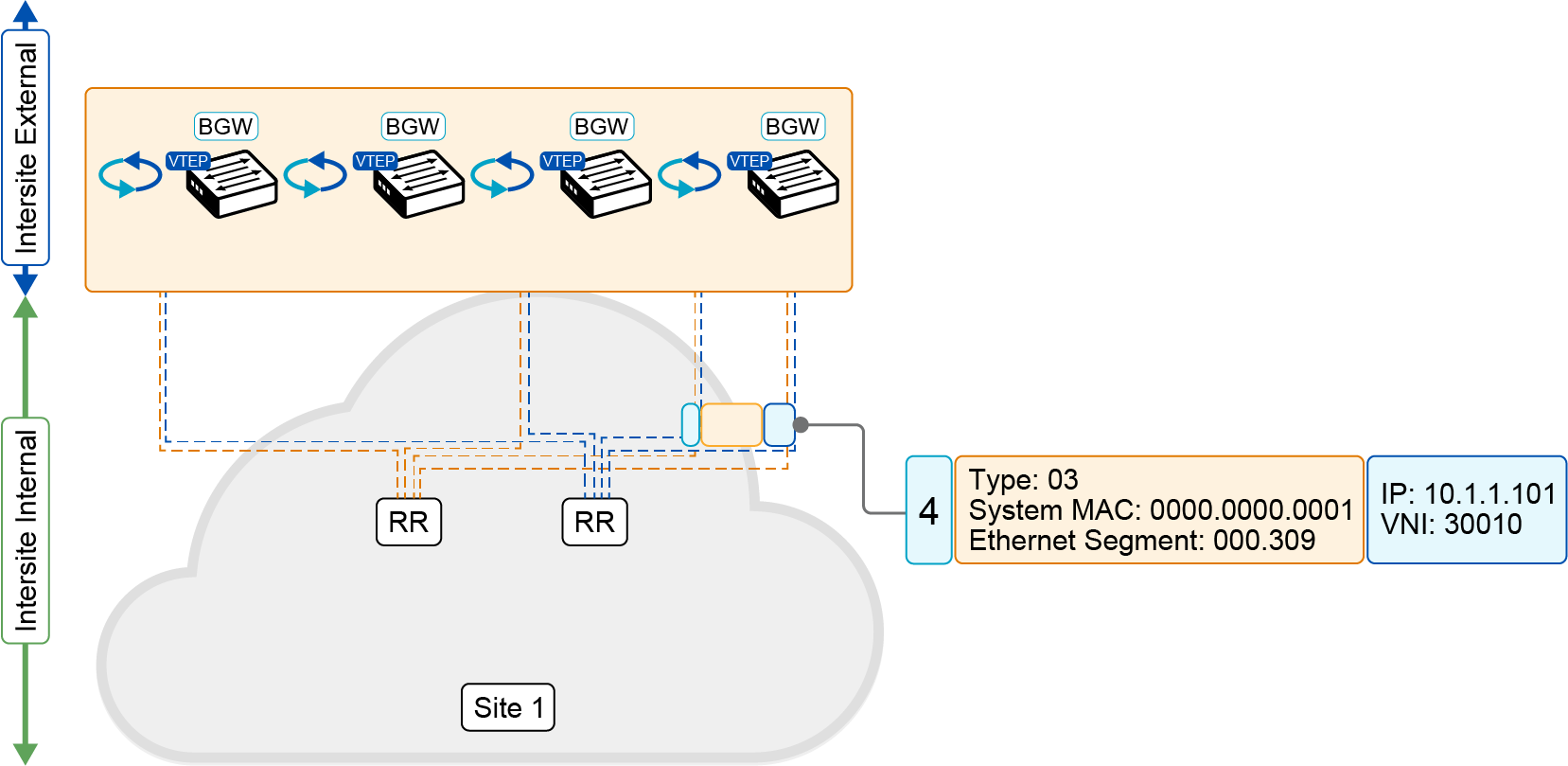
BGWs in the same site exchange BGP EVPN Route Type 4 updates to synchronize designated forwarders on the Ethernet segment.
To participate in the designated-forwarder election, the configuration of the same site ID is required. This ID is defined as part of the BGW configuration (evpn multisite border-gateway site-id). In addition to the site ID, the same Layer 2 VNI must be used to elect the designated forwarder from among the eligible BGWs.
The designated-forwarder assignment is performed on a per-Layer 2 VNI basis, using a round-robin process to distribute assignments equally. An ordered list of PiP addresses is used. Based on the Layer 2 VNI configuration order, the designated-forwarder role is assigned in a round-robin manner.
BGP EVPN peering is required yo exchange the designated-forwarder election messages between the BGWs, because the election messages consist of BGP EVPN Route Type 4 advertisements.
The BGW would usually peer with a site-internal (fabric) route reflector, which also has all the endpoint information from within the site-internal VTEPs. With the route reflector already present in the fabric, and with all VTEPs, including the BGW, peering with it, the exchange of designated-forwarder election messages is achieved.
In cases where no route reflector exists, or where the route reflector is not capable of relaying BGP EVPN Route Type 4, an IBGP session is an acceptible an alternative. The IBGP peering must be EVPN address family-enabled and there must be a full mesh that is established between the loopback interfaces of the BGWs.