Overlay Network Design
There are multiple ways to implement overlay networks with multiple protocols to choose from. Each protocol has its own unique functionalities that can be quite complicated to understand. Understanding the protocol well is the key to creating a good design.
VXLAN is currently the most prominent and established protocol in the data center and can serve as the standard for solving challenges that are typically addressed by implementing overlay networks. However, VXLAN is not the only overlay that you can choose to implement in your data center design.
Each overlay network protocol has its own strengths and weaknesses. However, they all use the same basic design of encapsulating, transferring, and decapsulating traffic over the network underlay. Because of these common characteristics, they also share overall design considerations.
Consider the following aspects when designing overlay networks.
What does the physical underlay topology allow?
Overlay is always dependent on the underlay network. Considerations such as MTU, multicast capabilities, bandwidth, latency, traffic pathing, physical device capabilities, traffic processing capabilities—such as encapsulation/decapsulation, physical high-availability, and others, are all dependent on the physical hardware.
How is a logical underlay topology configured?
Overlays allow you to connect segments that would otherwise not be able to communicate. This ability to redirect traffic can often create load on network segments that previously did not see a lot of traffic. Any suboptimal routing or traffic processing limitations will not only affect the overlay, but also the underlay native traffic.
How will the traffic flow from the end-host to the overlay entry point?
Position of the overlay endpoints is key. The endpoint devices will need to perform the encapsulation/decapsulation and the amount of traffic that needs to be processed can vary depending on the topology and underlay configuration. It is often wise to create endpoints on the actual hypervisor environment to offload overlay traffic handling to the server. This is common in fully virtualized environments.
How are overlay entry points distributed in terms of load balancing?
How many paths will there be through the overlay and what are the physical link speeds for connections between end-hosts and the overlay tunnel endpoints. Multiple tunnel ingress and egress points can provide load balancing, such as with VXLAN MP-BGP EVPN overlay.
How are overlay entry points distributed in terms of high-availability?
Single overlay tunnel endpoints are single domains of failure. If the tunnel endpoint fails the connectivity over the overlay will not be possible. Similar redundancy considerations apply to standard networking. Multiple tunnel endpoints for a set of end-hosts are also useful for load balancing.
How will the native underlay traffic coexist with the overlay traffic
From the underlay network standpoint, the encapsulated traffic is typically just traffic. And all traffic needs to be processed. Overlay traffic can sometimes be of higher or lower importance than underlay native traffic. Consider using Quality of Service (QoS) classification and prioritization of different traffic types to adapt to the requirements of a specific overlay or underlay workload.
How will you provide workload mobility?
Extensions such as VXLAN Distributed Anycast Gateway can allow virtualized workloads, such as VMs, to move between physical devices that depend on different overlay tunnel endpoints. This flexibility is often important because workloads may need to be moved. You might relocate them to be closer together, onto a more powerful server, or into a different availability zone.
How many services are in an individual overlay endpoint domain?
Overloading individual tunnel endpoints with too many services will eventually cause issues. This may result from traffic congestion inside or outside the overlay, or from excessive local BUM traffic on a segment. Device hotspots and fragile designs that increase the impact of failures can also be causes. This issue can often be resolved through workload mobility.
How will security be enforced on the overlay?
Segmentation and policy enforcement can be complex to implement when you need to account for the overlay and underlay rules and concerns. Maintaining a secure environment can be challenging. That’s why using centralized, policy-based management in an SDN environment like Cisco ACI is very helpful.
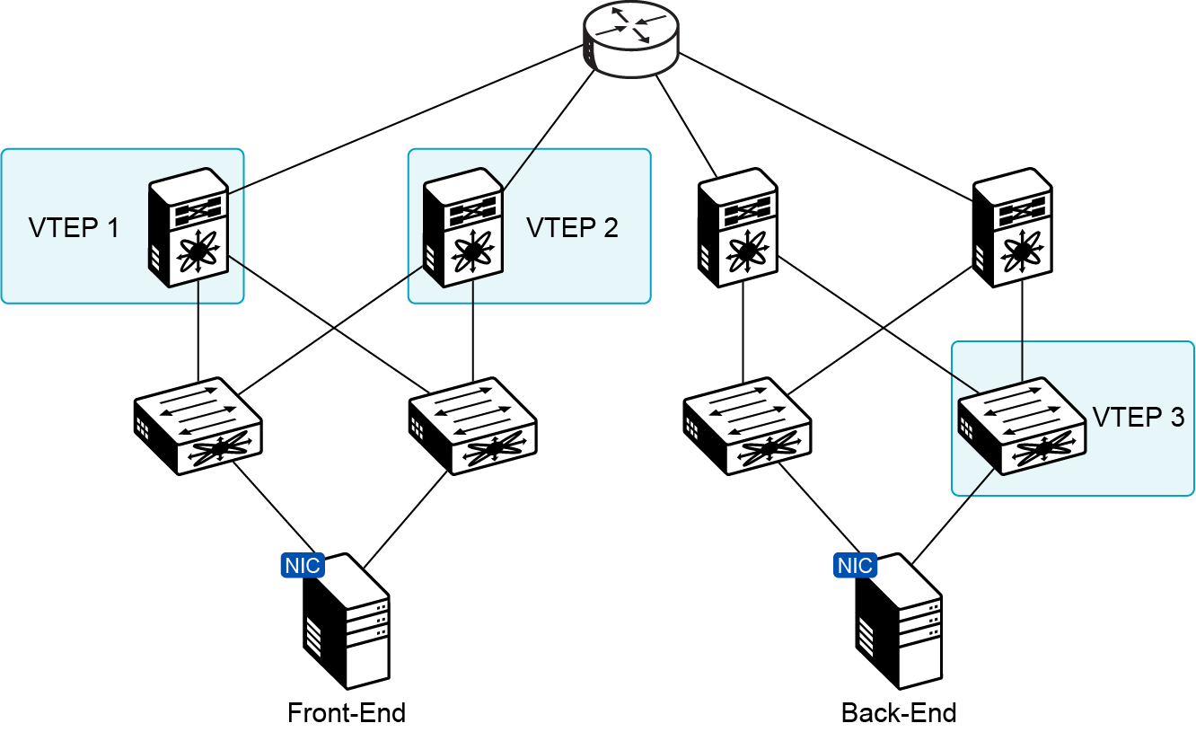
Segments that are too large, not highly available or workloads that communicate over bottle-necks show bad overlay design.
The image shows an example of bad overlay network design. There are two spine-and-leaf segments that are connected through a single router or a Layer 3 interconnect. From the physical topology standpoint, this is not necessarily a bad design, until you account for the overlay network and the workload communicating over the overlay network.
The workload in the example is split between front-end and back-end, which together from the application stack. However, the back end is dislocated from the front end, causing all communication between application components to traverse over the Layer 3 interconnect between infrastructures. A single router is a single point of failure, and a single device that carries all the traffic between the two sides.
The router in the topology will need to manage all the traffic from four spine switches, putting a lot of load on the single device. This will cause the device utilization to be on average very high, which can lead to potential device failures. If the intermediate router is not able to handle the traffic at any point in time, this will cause congestion in the network.
Network congestion is a big problem for split application back ends and front ends. It increases latency for database queries and adds extra load on the router.
The VTEP positioning in the topology is not ideal either. VTEP-3 is a single tunnel endpoint through which the server can communicate with the remote site. There is no high availability if the device configured with VTEP-3 fails. Also, virtualized server uplinks typically use pinning for communication with the network. This makes traffic patterns in this network suboptimal.
If back-end traffic uses the left server’s physical link, it must go through the spine switch. Only then can it reach VTEP-3.
In the left segment, the VTEPs are highly available, but are configured on the spine switches. This unnecessarily enlarges the number of devices that rely on VTEP-1 and VTEP-2. The drawn topology is simple but imagine that 50 leaf switches may be connected to the spines configured with VTEP-1 and VTEP-2 at some future point in time.
The configuration may not be problematic today, but having VTEPs on leaf switches would be much more scalable, since with additional leaf switches, additional VTEPs would automatically be added. I could also be beneficial to configure VTEPs on the servers themselves and use the switches in the topology for the underlay only.
Network Segmentation
Network segmentation refers to the practice of dividing a computer network into multiple smaller, isolated segments, each of which can have its own policies, security controls, and traffic rules.
Segmentation helps limit failure domains and prevent issues like broadcast storms. It also enforces security policies between segments and allows you to monitor and inspect traffic. Network segmentation also provides a way to implement multi-tenancy and compliance with different tenant requirements within a segment, while not affecting other segments.
Overlay networks encapsulate traffic and change its nature. This hides the real characteristics of the traffic, similar to how a VPN hides your activity on public Wi-Fi. This is why you need to consider the implications of creating an overlay on the underlay network and apply security policies on the underlay that account for the overlay.
The security considerations that apply to standard network design apply also to the network overlay. Overlays are typically primarily data-plane protocols, such as VXLAN. You can segment the network into different VNIs. However, most overlay protocols don’t have policies or rules to control which devices in one segment can communicate with those in another.
For this reason, you are still limited by the underlay filtering and policy enforcement capabilities. Unfortunately these are more costly to perform in most cases, since you need to further inspect a VXLAN encapsulated transmission compared to a non-encapsulated transmission to account for the encapsulation.
SDN solutions address this by using policy-based configuration and a central management plane. This extends control plane capabilities to set and enforce policies on overlay network traffic.
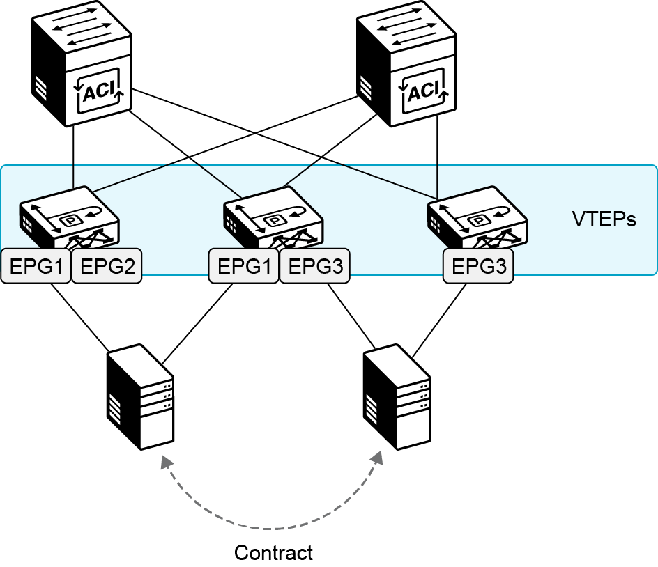
Cisco ACI applies policies and enforces communication between End-Point Groups (EPGs) using contracts.
Cisco ACI solves many design issues when setting up VXLAN infrastructures. Its standardized design also lets you enforce communication policies on the ACI VXLAN overlay fabric.
Segmentation mechanisms in ACI enable you to isolate and enforce traffic rules.
Tenants
Is the highest level of segmentation. Separates all policies between tenants and provides isolation between environments.
VRFs and Bridge Domain segmentation
This is segmentation inherited from VXLAN operation, it enables segment separation, so that you may apply policies between segments.
EPG core policy segmentation
EPGs are sub-divisions inside Layer 2 or Layer 3 segments determined by VRF and bridge domain separation.
Contracts & filtering
Contracts are policy bundles that determine communication between EPGs. They also include filtering capabilities based on the traffic characteristics, such as ports, and IP addresses.
Intra-EPG isolation
Optional feature that can be enabled to disallow communication between end-hosts inside the same EPG. You can imagine an EPG as a group of ports on a device.
Microsegmentation and Application Profiles
You can segment an EPG into microsegments. A uSEG EPG is segmented further and gives control over hypervisor-level network objects. Such as port groups inside a vSphere environment.
Service graph traffic redirection
Part of contracts, allows redirection of traffic through a firewall, packet inspector, load balancer, or a similar service. It allows further packet processing by redirecting traffic to a custom service.