VXLAN Data Plane
Once the VXLAN control plane is updated with VTEP and end-host information, the overlay connections between VTEPs can be established. Usually by the network devices in the topology, unless you are running a fully virtualized workload. Underlayer network capabilities are still used to optimize the amount of VXLAN encapsulation. For example, you do not want to encapsulate traffic that terminates within a single VTEP, just to have it decapsulated in the same VTEP.
When you configure the VXLAN protocol, your switch forwards traffic differently depending on the destination MAC address and learned VXLAN topology. If the source and destination MAC addresses are available on the same VLAN and the switch has already learned those MAC addresses, it forwards traffic locally with no VXLAN encapsulation.
If your switch’s VXLAN tunnel table shows that the destination MAC is behind a remote VTEP, it adds a VXLAN header to the frames. It then forwards them to the remote VTEP.
The remote VTEP decapsulates the VXLAN packet and forwards the inner frame to the port where the recipient is connected. If the local VTEP does not know the destination MAC address, further steps depend on the control plane implementation.
There are three options for handling frames whose destination is unknown to the local VTEP:
MP-BGP EVPN: Unicast frames with an unknown destination MAC address are dropped. The host information is learned though MP-BGP, not flooding.
Flood-and-Learn: Unicast frames with an unknown destination MAC address are forwarded using a predefined multicast group.
Head-End Replication: Unicast frames with an unknown destination MAC address are replicated to all corresponding VTEPs using multiple unicast packets.
Head-End Replication (HER) is used in situations where the underlay network does not support multicast. HER enables traffic to be forwarded to each VTEP through unicast.
The action taken by VTEP to update its VXLAN MAC table makes the remote packet destination known to the VTEP for VXLAN encapsulation.
VXLAN Unicast Forwarding Layer 2 Packet Flow
When your VTEPs have collected all the necessary information about end host and virtual machine MAC addresses, you can start encapsulation traffic and forwarding it to the destination VTEP.
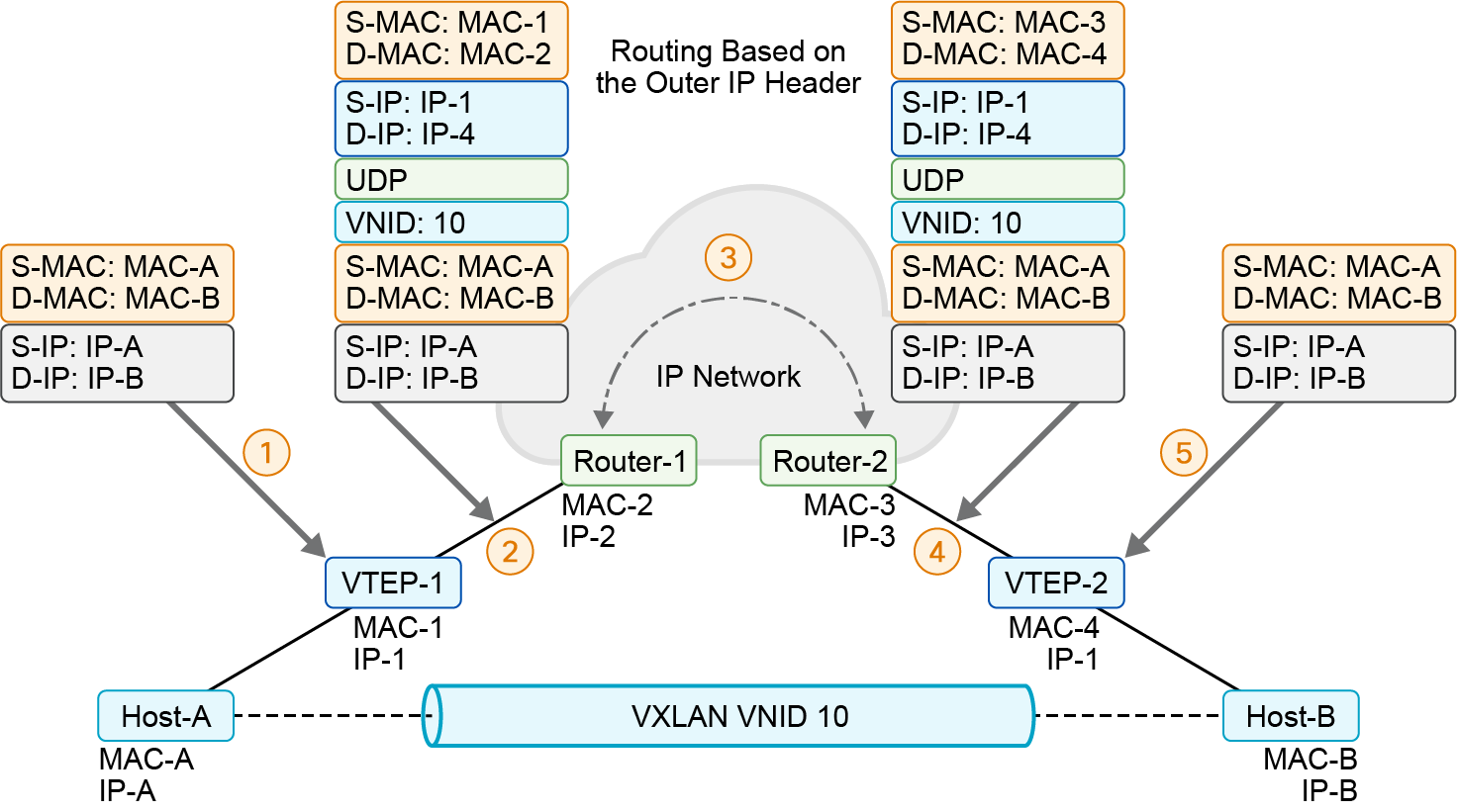
Layer 2 from the same frames are sent in Layer 3 packets over the VXLAN overlay to the remote Layer 2 segment.
In the preceding example scenario, you have two end hosts: Host-A and Host-B reside in the same subnet but are behind different VTEPs. Host-A sends a Layer 2 frame to Host-B. In the example, the traffic still has Layer 3 destination included. The example shows traffic processing within the same VLAN stretched over an overlay.
The traffic forwarding process within the same Layer 2 segment has the following steps.
Step 1
Host-A sends a Layer 2 frame with its own source MAC and IP addresses; the destination MAC and IP addresses are the addresses of Host-B. Based on the switching tables of local switches, that original frame will come to the local VTEP-1.
Step 2
VTEP-1 looks in its local MAC address table and finds that the destination MAC address is located behind remote VTEP-2. VTEP-1 encapsulates the original Layer 2 frame with VXLAN, UDP, IP, and Ethernet headers and sends it through the transport IP network to the remote VTEP-2. Because Host-A belongs to VXLAN 10, the VTEP uses VNID 10 in the VXLAN header. In the outer IP header, VTEP-1 uses its own IP address as the source and uses the IP address of VTEP-2 as the destination. In the outer Ethernet header, VTEP-1 uses its own MAC address as the source and the MAC address of the next-hop router as the destination MAC address.
Step 3
The VXLAN packet will travel through the underlay transport IP network from VTEP-1 to VTEP-2.
Step 4
Router-2 has VTEP-2 as the next hop router. Router-2 forwards the encapsulated packet to the VXLAN tunnel destination.
Step 5
VTEP-2 decapsulates the packet, verifies its local MAC address table, and forwards the original Layer 2 frame to its final destination, which is Host-B.
Because in the example both hosts belong to the same subnet, traffic behavior looks like they reside on the same switched physical network. The Layer 3 overlay is invisible to the end hosts.
Although VXLAN is very performant in proper implementations, it still relies on routing over the underlay network, which can add latency and processing overhead. Although the end hosts are unaware of the VXLAN transport, the underlay still needs to process the traffic.
VXLAN Unicast Forwarding Layer 3 Packet Flow
Transferring traffic between different Layer 2 segments (different subnets) needs to also include routing in the transport in addition to the Layer 2 transfer. In a scenario where Layer 2 VNIs are different between the local and remote host, VXLAN initiates Layer 3 routing.
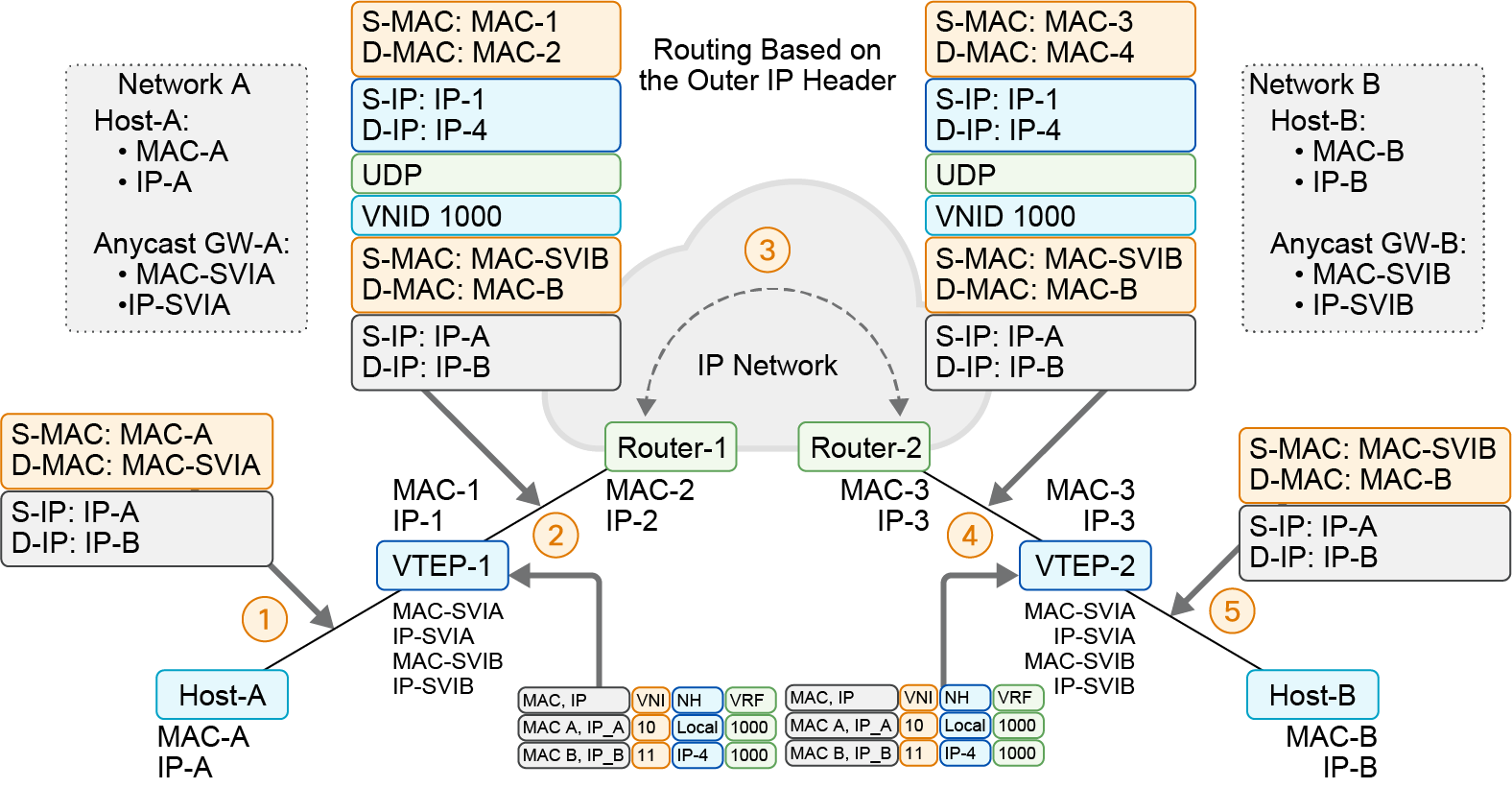
VXLAN uses Virtual Routing and Forwarding instances mapped to Layer 3 VNI to perform routing.
Host-A (attached to VTEP-1) belongs to the Layer 2 virtual network with VNI 10, and Host-B (attached to VTEP-2) belongs to the Layer 2 VNI 11. The subnets for the two networks host different IP address ranges, so the traffic between them is routed.
MP-BGP EVPN has sent the reachability information for the two end hosts. This includes the Layer 3 VNI, MAC and IP addresses, and the SVI subnet address. The ARP and forwarding tables of the source and target switch VTEPs are populated with the end host reachability information.
The traffic forwarding process in this case has the following steps.
Step 1
When Host-A sends traffic to VTEP-1, the destination MAC address of the packet is encapsulated with the MAC address of the (distributed IP anycast) gateway.
Step 2
VTEP-1 does a lookup, notes the VTEP to which Host-B is attached, and checks the VRF (and associated Layer 3 VRF VNI). VTEP-1 VXLAN encapsulates the traffic that Host-A sends and sends it to VTEP-2.
Step 3
The routed traffic from VTEP-1 to VTEP-2 logically traverses through the Layer 3 VRF VNI 1000. Practically, the traffic traverses through the underlay.
Step 4
When the packet reaches VTEP-2, VTEP-2 does a control plane lookup, notes that Host-B’s IP address is in VRF 1000, and then does a MAC table lookup for Host-B. After VTEP-2 identifies the port to which Host-B is attached, the packet is sent to Host-B.
When Host-A sends traffic to VTEP-1, the destination MAC address of the packet is encapsulated with the MAC address of the (distributed IP anycast) gateway.
Cisco Nexus Spine-and-Leaf Deployment with VXLAN Overlays
Cisco Nexus switches natively support VXLAN overlays. You can configure these overlays manually through the command-line, however this can be time-consuming and difficult to maintain, especially on a large scale. Manual configuration is useful if you need small-scale VXLAN connectivity between a limited number of VTEPs.
When you want to implement VXLAN on a large scale, it is much more efficient to use a central management system to deploy the VXLAN fabric. With Cisco Nexus 9000 switches, you can use Cisco Nexus Dashboard to create VXLAN fabric on any topology, or Cisco ACI for a dedicated policy-based SDN solution.
Cisco ACI can also be registered to Cisco Nexus Dashboard, so that you can manage several different network topologies together, regardless if they use VXLAN or not.
Although you can implement VXLAN on almost any topology, the spine-and-leaf topology provides a perfect physical underlay for VXLAN. It is simple to scale and deploy. It has high throughput and excellent resiliency while maintaining simplicity, where endpoints are clearly defined and the possible paths between them easy to understand.
Cisco Nexus switches can be used with Virtual Extensible LANs (VXLAN) to extend the Layer 2 boundaries of a network across a large data center and across different data centers. Therefore, this solution can provide VM-to-VM communication in a scalable way. For example, it can facilitate a multitenant environment where the available 4000 VLANs do not scale well. Cisco Nexus switches can act as the VXLAN overlay tunnel termination point.
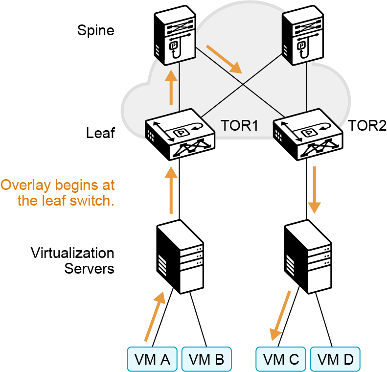
In spine-and-leaf topology typically each leaf represents a VTEP and acts as the VXLAN overlay entry point.
The leaf switches provide the VXLAN Tunnel Endpoints (VTEP) for the VM-to-VM communication, such as during packet forwarding between VM A and VM C. Thus, the overlay begins at the leaf switches. The overlay operation ensures that the original frame or packet content is not exposed to the underlying IP network. The IP network that sends packets from TOR1 to TOR2 is based on the outer packet source and destination addresses forms the underlay operation.
When there is a requirement for routing between VXLANs, or routing out of the VXLAN, a VXLAN Layer 3 default gateway is required. During the VXLAN routing process, the VXLAN packets are de-encapsulated. The switch performs VLAN routing, then encapsulates the VLAN packets again into a VXLAN.
Since routing happens within the VLAN, there are different ways to terminate the VXLAN default gateway. This allows the decapsulated VLAN packet to be routed. This functionality can be implemented on the leaf or on the spine switches. If the spine is chosen, routed traffic needs to traverse only one hop to reach the default gateway at the spine switches to be routed.
However, when you are using the spine switches for the default gateway, the spine can only be two switches wide, which limits the size of the topology. If the gateway is on a leaf, then the spine can be grown or widened as required. Although in this situation, two hops are required to get to the gateway for the internal VXLAN routing.
For routing out of the VXLAN, the Layer 3 gateway can also serve as the Layer 2 gateway. In this case, the VXLAN is converted to a VLAN, which is then routed out of the spine-and-leaf fabric.
VXLAN fabric passes traffic without altering it, making it appear as if it moved through a traditional network. This lets VXLAN SDN solutions like Cisco ACI integrate easily with existing infrastructure. The ACI system is also compatible with more traditional protocols such as vPC and Spanning-Tree Protocol.