Cisco ACI Architecture
Cisco ACI (Application-Centric Infrastructure) is a Software-Defined Network overlay that uses VXLAN and a spine-and-leaf topology. Cisco offers it as an end-to-end solution for deploying, managing, maintaining, and scaling VXLAN SDN.
Cisco Application Centric Infrastructure (ACI) uses CLOS topology, VXLAN, and MP-BGP EVPN for its control plane. It provides an integrated, easy-to-deploy SDN solution for modern data centers.
Cisco Application-Centric Infrastructure (ACI) in the data center is a holistic architecture with centralized automation and policy-driven application profiles. It gives the administrator the power to simply establish connectivity between various endpoints and provides a unified way to manage endpoints by assigning them to endpoint groups (EPG).
EPG is a management construct that defines a connectivity group that has the same traffic characteristics, rules, and policies. EPGs enable management of end-host connectivity at scale.
Policies define the communication rules for EPG-to-EPG communication, specifying what can connect where and how. A set of these policies is called a Contract.
Cisco ACI uses the standard protocol stack but adds an integrated control and management plane. Its policy model turns VXLAN into a full SDN and applies consistent, simple policies across the entire infrastructure.
This system-based approach simplifies, optimizes, and accelerates the entire application deployment lifecycle across data center, WAN, access, and cloud environments. In doing so, this system empowers IT to be more responsive to changing business and application needs. This ability enhances agility and adds business value.
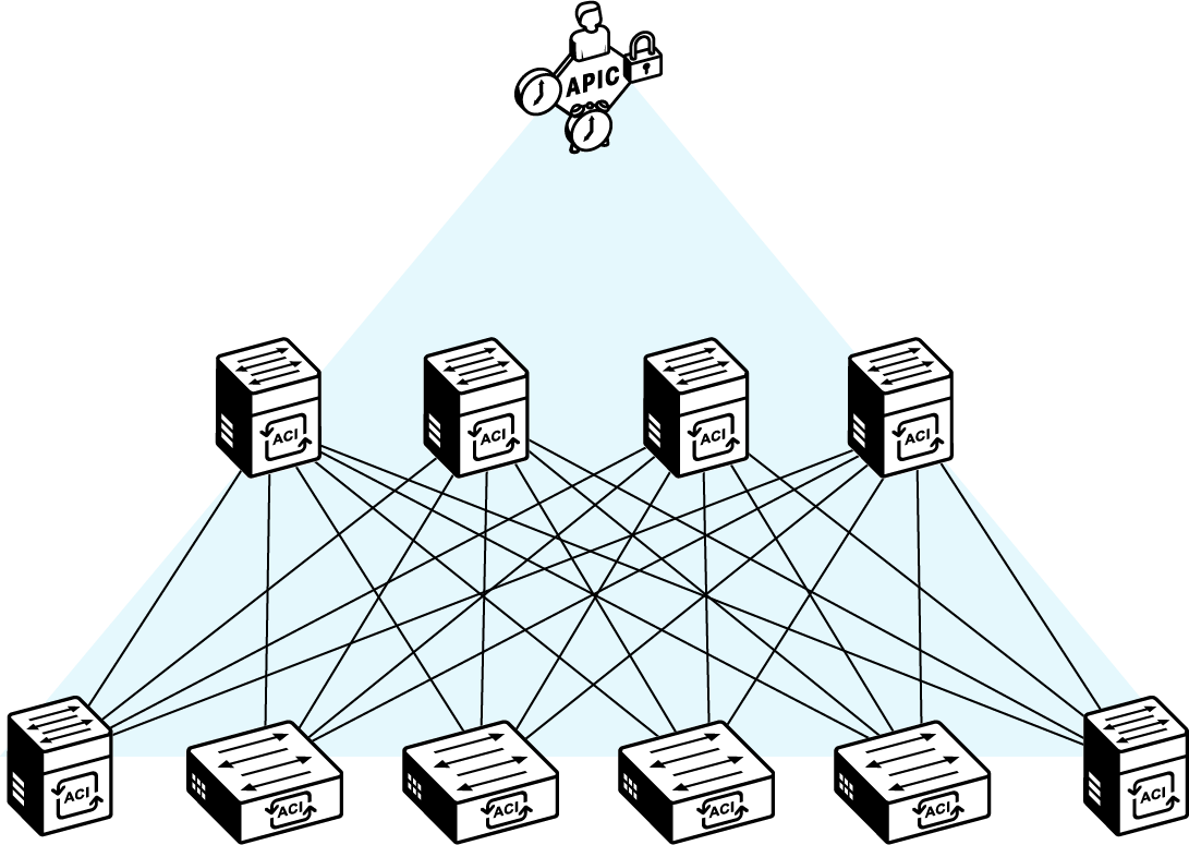
A Cisco APIC centrally manages an ACI fabric made up of spine and leaf switches organized in a CLOS topology.
The design of Cisco ACI is based on the fabric as a whole, as opposed to treating the fabric switches individually. All individual physical components comprise the overall system. Cisco ACI supports traditional, virtualized, and next-generation applications by removing the restrictions of classical networking.
Cisco ACI fabric uses a spine-and-leaf topology. The high-bandwidth links between the spine and leaf switches provide transport to an integrated overlay that is used by host routing. All host traffic that arrives at the ingress leaf is carried over an integrated overlay. All endpoints connect to leaf switches, which offer high port density. Spine switches, with at least two for redundancy, aggregate the fabric bandwidth. The fabric can support an arbitrary number of tiers and partial mesh if required.
The Cisco ACI fabric is composed of the Cisco Application Policy Infrastructure Controller (APIC) and the Cisco Nexus 9000 Series spine and leaf switches. The leaf switches are connected to the spines, but never to each other in a CLOS topology. The spines are attached only to the leaf switches. The Cisco APIC and all other endpoints and devices in the data center are connected only to the leaf switches. The leaf-only connectivity approach is seen in the figure.
Leaf switches act as VXLAN overlay VTEPs. Links between spine and leaf switches are dedicated to VXLAN transport and use ECMP for load balancing. The spine switches process the traffic and enforce traffic policies that are configured on the fabric.
Spine switches represent the control plane of the fabric and run the VXLAN MP-BGP EVPN control plane. Other control plane extensions complement this control plane. Examples include IS-IS for intra-fabric routing, L3Out protocols for external routing, and OpFlex for orchestration.
The administrator applies policies and connectivity rules through a central GUI of the APIC controller. The APIC controller stores all configuration and applies it to the entire fabric. Users do not need to change individual ACI fabric devices. The user defines the intent, such as "EPG-A can speak to EPG-B" and this is translated into fabric configuration and applied by the APIC controller.
The Cisco APIC is a policy controller that relays the intended state of the policy to the fabric. It does not represent the control plane and does not sit in the traffic path. The hardware consists of a cluster of three or more physical servers or virtual machines in a highly redundant array. The APIC controller is mandatory for an ACI deployment.
The characteristics of the Cisco APIC are as follows:
Intent-based policy controller
It is the intent-based policy controller.
It holds all the defined policies.
It represents the management plane, not the control plane, and is not located in the traffic path.
It instantiates the policy changes.
It monitors the fabric state and provides user-feedback.
It provides the GUI for user interaction with the fabric.
It provides the API target for automation and orchestration.
Deployed as a redundant cluster
It is deployed as a redundant cluster of three or more physical or virtual servers.
Each APIC server is dual homed to two leaf switches in the fabric for resilience.
It holds all the defined policies.
It represents the management plane, not the control plane, and is not located in the traffic path.
It instantiates the policy changes.
It monitors the fabric state and provides user-feedback.
It provides the GUI for user interaction with the fabric.
It provides the API target for automation and orchestration.
APICs in a cluster form a quorum for stored configuration data across controllers.
Cisco APIC hardware appliance is delivered on Cisco UCS C-Series server system. The product consists of the server hardware and preinstalled bare-metal Cisco APIC software.
Virtual APIC controllers are provided as VM virtual appliances and can complement the physical deployments to provide high availability. Virtual appliances run inside a hypervisor or a container environment. Using at least one physical appliance APIC is recommended for the best resiliency and reliability of the management plane.
Refer to Cisco ACI Virtualization Compatibility Matrix for more information on supported virtual environments:
Cisco ACI Multi-Pod Deployment
Cisco ACI can be integrated into multiple individual physical network segments interconnected with an upstream network system as the interpod network (IPN). From the management standpoint this multi-segment deployment, called ACI Multi-Pod, is a single management domain with controllers distributed across the physical segments.
The Cisco Application-Centric Infrastructure (ACI) Multi-Pod design uses a single Cisco APIC cluster to connect separate ACI fabrics, called pods. Each pod has its own leaf-and-spine two-tier architecture.
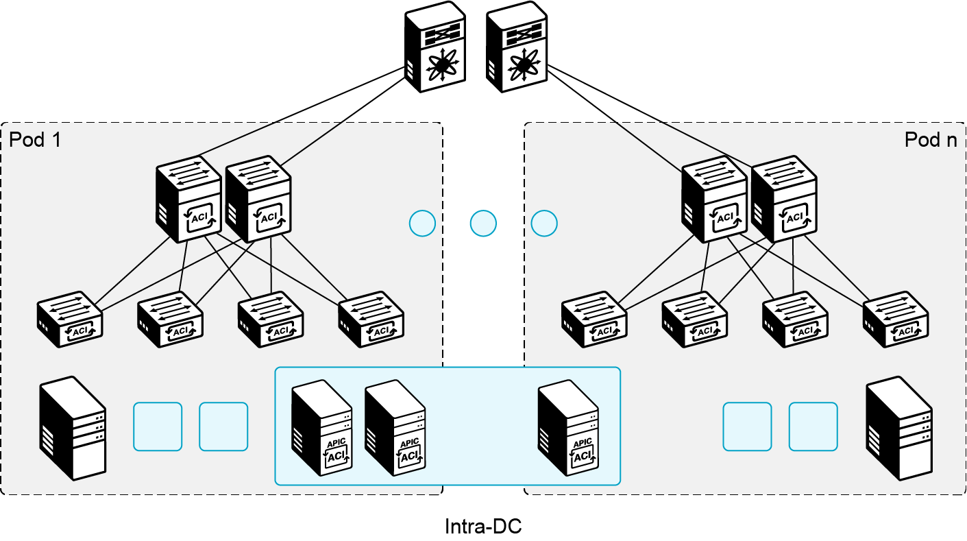
Leaf switches may reside in different buildings or floors, while pods connect to each other through spine switches located in their respective pods.
Along with leaf and spine switches, a single Cisco APIC cluster manages all interconnected ACI pods. Individual APIC controllers are placed across the pods for this purpose.
You can provision WAN routers in the interpod network (IPN) while directly connecting them to the spine switches, or you can provide WAN connectivity through the border leaf switches.
Furthermore, the Cisco ACI Multi-Pod provides a fault-tolerant fabric, because each pod has isolated control plane protocols.
Cisco ACI Multi-Pod lets you connect fabrics in different data centers, usually within the same metro area. These are linked through point-to-point connections like dark fiber or DWDM circuits. The maximum supported latency between pods is 10 msec RTT. The link between the spine switches and routers in the same location is typically 40/100G, while the interconnecting link between the data centers is 10/40/100G.
The IPN devices connect different Cisco ACI pods and provide pod-to-pod communication (east-west traffic) as an extension of the Cisco ACI fabric underlay infrastructure. Therefore, the IPN must support several specific functionalities to perform those connectivity functions, such as the following:
Multicast
DHCP relay
OSPF
Increased MTU
QoS
Losing a single Cisco APIC controller in any pod (with three or more controllers) does not affect operations. The cluster still has a quorum, such as two out of three controllers. So, you can continue to make configuration changes because all shards are in read/write mode.
If two controllers fail, some data (with more than three controllers) or all data (with three controllers) will be read-only. This happens because the replicas on the failed controllers are missing. Therefore, if you have a three-node cluster, you cannot make any configuration changes until at least one of the controllers is restored. The best practice is to promptly bring the Cisco APIC nodes online, so the Cisco APIC cluster is restored to full health.
A pod failure scenario may occur when an entire site goes down because of a disaster (fire in the data center or a whole building, flood, earthquake, and so on). In this case, there is a significant behavioral difference between a three- or five-node Cisco APIC cluster that is stretched across pods.
In a three-node Cisco APIC cluster, losing the pod with one controller has no impact. This is similar to losing a single Cisco APIC controller in one location. If the pod with the most nodes fails, all data on the Cisco APIC node in the other pod goes into read-only mode. If a pod is down and will take time to recover, you can use a standby controller in the second pod. Promote it to active to restore quorum for the Cisco APIC controllers.
Cisco ACI multisite Deployment
The ability of VXLAN topologies to span multiple sites is also present in Cisco ACI. ACI uses a separate VXLAN tunnel to interconnect sites, however the protocol and management stack is the same for both network overlays.
Cisco ACI multisite deployment uses a higher-layer orchestration to apply policies across multiple sites and a VXLAN MP-BGP control plane between sites to exchange host reachability information.
The policy manager in ACI multisite is the Cisco Nexus Dashboard Orchestrator. The Cisco Nexus Dashboard Orchestrator (NDO) is an external system for multisite management. It is part of the Cisco Nexus Dashboard platform and can run as a physical appliance or a virtual appliance in a hypervisor environment.
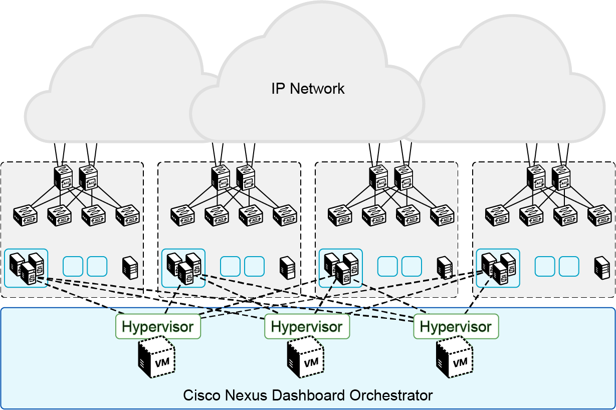
ACI multisite interconnects fully autonomous ACI topologies and manages them centrally through the Cisco Nexus Dashboard Orchestrator.
Cisco ACI multisite lets you connect separate ACI APIC cluster domains, with each fabric as a different availability zone. This creates multitenant Layer 2 and Layer 3 connectivity across sites using a unified end-to-end policy.
You can use the Cisco ACI multisite policy manager to define intersite policies. These policies can be deployed across separate ACI fabrics, even though each site has its own APIC cluster domain.
Sites exchange endpoint reachability information using an MP-BGP EVPN connection. Layer 2 or Layer 3 communication between endpoints in different sites uses site-to-site VXLAN tunnels over an IP network.
You do not need to connect every spine node in the sites to the external IP network. You can choose the number of spines and links for connecting to the external IP network. Base your decision on your available hardware and your desired resiliency and throughput. Furthermore, you can scale up the total number of leaf-and-spine nodes that are deployed across the interconnected fabrics and the total number of endpoints. This scalability is an advantage compared to the Cisco ACI Multi-Pod designs, which inherit the scalability restrictions of a single fabric design.
The Cisco ACI intersite policy manager (Cisco Nexus Dashboard Orchestrator) lets you provision and manage Cisco ACI networking and stretched tenant policies across sites. It also lets you monitor their health and manage their full lifecycle. It provides a GUI for configuration and monitoring of your Cisco ACI and Cisco APIC implementations and is arranged according to different functionalities.